A water main break at 2 a.m. presents a binary choice: shut down service to 50,000 people while your crew digs, cuts, and patches — or find a way to stop the leak under live pressure. For most municipal water utilities, the answer has shifted decisively toward live-line repair. The equipment exists, the techniques are proven, and the cost of service interruption (flushing dead-end mains, compensating affected businesses, repairing pressure-related damage) typically far exceeds the cost of the right repair hardware.
This guide covers the complete live-line repair workflow: leak classification, product selection, installation procedure, and the conditions under which shutdown is genuinely unavoidable.
What counts as a “live-line” repair?
Live-line (also called pressurized or no-dig) repair means making a permanent or long-term repair to a pipe that remains pressurized throughout the operation. The crew never vents the line to atmosphere during the critical sealing step.
This is distinct from:
- Emergency isolation + repair: shutting a zone valve, reducing pressure to zero, making the repair, then restoring. This is a shutdown repair even if it only affects a zone.
- Live tapping: drilling into a pressurized main using a hot tapping machine. This is live-line work but covers new connections rather than leak repair.
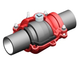
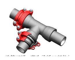
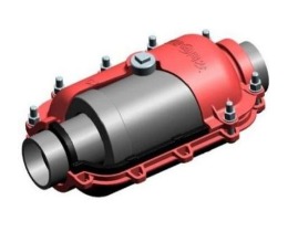
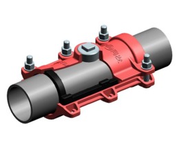
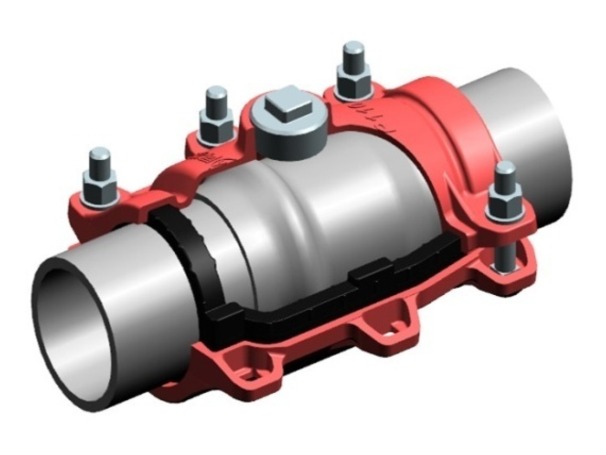
True live-line repair requires a containment seal that can be applied over the outside of the pipe while internal pressure holds. The primary tool for this is the split-sleeve repair clamp (also called a haff clamp, repair coupling, or encirclement clamp).
Step 1: Classify the leak before you order anything
Before calling for product, you need to know:
Leak geometry
- Circumferential crack — runs around the pipe’s circumference, typically at a joint (bell-and-spigot) or a casting defect. Requires a socket-type or wide-body clamp.
- Longitudinal crack — runs along the length of the barrel. Usually less common; requires a sleeve clamp long enough to bridge the full crack length plus 100–150 mm each side.
- Pinhole / corrosion pit — localised pitting from external or internal corrosion. A short sleeve clamp suffices, but check surrounding wall thickness: if pitting is widespread, a sleeve clamp is treating a symptom.
- Joint failure — the seal at a mechanical joint, flanged joint, or push-fit socket has failed. May need a dedicated socket repair clamp rather than a barrel clamp.
Pipe material and OD
Repair clamps are designed around the outside diameter (OD) of the pipe, not the nominal diameter (DN). Ductile iron, grey cast iron, steel, HDPE, and PVC all have different ODs for the same DN. Measure the actual pipe OD with a circumference tape (wrap around and divide by π). Do not trust as-built drawings — older pipe has often been relaid and the material changed.
Operating pressure
Confirm the maximum allowable operating pressure (MAOP) at the repair point. The repair clamp’s pressure rating must meet or exceed this, with a safety factor. Most municipal distribution systems run at 0.3–0.8 MPa. High-pressure transmission mains can run at 1.0–1.6 MPa. Industrial and gas applications may run higher.
Temperature and fluid type
EPDM rubber seals are the standard for potable water service (up to approximately 120°C continuous). For gas lines, NBR (nitrile) seals are required for petroleum-based gases; EPDM is acceptable for natural gas in many standards. For aggressive chemical service (acids, chlorinated solvents), consult the manufacturer.
Step 2: Select the right clamp
The following table covers the most common leak scenarios and their standard product match:
| Leak type | Pipe material | Recommended product |
|---|---|---|
| Barrel crack or pinhole | Ductile iron | Straight-pipe sleeve repair clamp (DI) |
| Barrel crack | Grey cast iron | Straight-pipe sleeve repair clamp (CI) |
| Bell-and-spigot joint failure | Ductile iron | Socket (spigot) repair clamp |
| Bell-and-spigot joint failure | Grey cast iron | Cast iron socket repair clamp |
| Barrel crack | Steel | Steel pipe repair clamp (SS316 hardware) |
| Barrel or joint | HDPE / PE | Universal repair clamp with wide-range gasket |
| Multiple pinholes, short section | Any | Sleeve clamp wide-body version |
Key sizing parameters to give your supplier:
- Pipe OD (measured, not nominal) — or the OD range if you’re dealing with a multi-year procurement
- Crack/defect length — the clamp sleeve must extend at least 75–100 mm beyond each end of the defect
- MAOP — confirm the pressure rating you need
- Fluid: potable water, raw water, gas, or chemical
- Bolt material preference: standard carbon steel + hot-dip galvanising is fine for buried service; 304 or 316 SS hardware for above-ground, coastal, or gas applications
Step 3: Prepare the work zone
Live-line repair sounds simpler than it is from a logistics standpoint. The pipe is under pressure. A mishandled situation can escalate quickly. Before placing the clamp:
Excavation: Expose at least 600 mm of pipe on each side of the defect. If the defect is at a joint (bell and spigot), expose the full bell. You need enough working room to position the clamp, align the gasket, and torque the bolts without interference.
Pipe cleaning: Wire-brush the OD in the area where the gasket will seat. Remove rust scale, bitumen coating lumps, and loose tuberculation. The gasket does not need a mirror finish, but it cannot seal against loose debris or sharp raised edges that would prevent even compression.
Measure the OD again: Once the pipe is exposed and cleaned, re-measure. Corrosion, external coatings, and scale can add several millimetres to the OD. If your measurement puts you near the upper end of the clamp’s stated OD range, flag this before installation.
Standby isolation: Even when you plan a live-line repair, identify which valves would isolate the section if something goes wrong mid-installation. Brief your crew. If your isolation valves are seized or unknown, pressure-test the isolation path before you begin.
Step 4: Install the split-sleeve clamp
The general procedure applies to most ductile iron and cast iron split-sleeve designs:
-
Open the clamp: Hinge the two halves open. Inspect the EPDM gasket — it should be seated in its groove without gaps or folded edges. Do not apply lubricant to the gasket unless the manufacturer specifies a compatible lubricant (silicone-based is typical for EPDM; petroleum-based lubricants degrade EPDM over time).
-
Position over the leak: Place the lower half under the pipe. Centre the clamp over the defect so the defect is within the gasket’s sealed band, not at the edge. For a circumferential joint crack, the gasket must fully overlap the joint bell on both sides.
-
Close the upper half: Align the hinge and place the upper half. The two shell halves should seat flush — if there is a visible gap, recheck that the gasket has not folded under the shell edge.
-
Finger-tighten all bolts first: Thread all bolts with washers finger-tight before applying torque. This ensures the gasket compresses evenly rather than being driven into the pipe on one side.
-
Torque in a cross pattern: Using a calibrated torque wrench, tighten bolts in a crossing pattern (first bolt, then the bolt diagonally opposite, then adjacent, and so on). This prevents the shell from cocking and causing uneven gasket compression. Apply torque in stages: 30% of target, then 60%, then 100%.
-
Target torque values: Follow the manufacturer’s torque specification. For a typical DN200 ductile iron sleeve clamp with M20 bolts, this is commonly 100–130 N·m. Do not exceed the specified torque — overtightening can crack the bolt bosses on cast housings.
-
Leak check: Once all bolts are at specified torque, observe the joint for five minutes. For low-pressure distribution mains (under 0.6 MPa), a properly installed clamp typically stops all visible leakage within 2 minutes. If seepage continues at one edge, retorque that end’s bolts by 10% and observe again.
-
Backfill: Once the joint passes visual inspection, backfill with granular material to the manufacturer’s recommendations. Most clamps can be installed and backfilled within the same shift.
Post-installation pressure test
For larger-diameter mains (DN400 and above) and higher-pressure systems, a formal pressure test is recommended before returning the main to service. The test is conducted at 1.5× MAOP for 30 minutes with no visible leakage. This mirrors the factory hydrostatic test procedure and provides documentary evidence for the utility’s maintenance records.
When live-line repair is not enough
Live-line repair is appropriate for most isolated defects on pipe in otherwise sound condition. It is not appropriate when:
- The pipe wall is extensively corroded: if the measured remaining wall thickness is less than 50% of the original, a sleeve clamp is concealing a broader problem. Plan a pipe section replacement.
- The defect is a weld crack on a high-pressure steel main: steel mains above 1.0 MPa with weld cracks may require radiographic examination and weld repair before a mechanical clamp is applied.
- The joint has completely separated: if the spigot has pulled out of the bell, there is no pipe surface for the gasket to seal against. You need a complete joint reassembly.
- Simultaneous multiple failures: three or more defects in a 10-metre run suggests systemic deterioration. Document and recommend for lining or replacement, not point repairs.
- The leak is on a gate valve or air valve: clamps seal pipe barrel OD. They cannot seal valve bodies.
Special case: live-line repair on gas mains
The same split-sleeve principle applies to gas distribution mains, with additional precautions:
- No spark-generating tools in the excavation: use non-sparking wrenches, brushes, and lighting. All electrical equipment must be rated for hazardous locations.
- Continuous gas monitoring: maintain continuous monitoring during the repair. Evacuate the excavation if gas concentration exceeds 10% of the lower explosive limit (LEL).
- NBR gaskets for petroleum-based gas: methane (natural gas) is compatible with both EPDM and NBR. LPG (propane, butane) requires NBR.
- Regulatory notification: most jurisdictions require notifying the gas safety authority before commencing live-line repair work on gas distribution mains. Do not rely on internal utility authorisation alone.
Crew competency and documentation
Live-line repair is a trained-crew activity. The critical failure modes — gasket folding, uneven torque causing shell cocking, incorrect clamp sizing — are all preventable with proper training and a pre-installation checklist.
At minimum, the repair record should document:
- Date, time, and work order number
- Pipe OD measured on site, pipe material, and operating pressure
- Clamp model, manufacturer, catalogue number, and serial/batch number
- Bolt torque achieved and method (calibrated torque wrench number)
- Post-repair observation period and outcome
- Name and certification of the lead technician
This documentation protects the utility in the event of a subsequent failure at the repair point and provides the data needed to evaluate whether a clamp type is performing as expected across the system.
PipeKnot stocks repair clamps for ductile iron, grey cast iron, steel, and HDPE mains from DN40 to DN2000. If you need help sizing a clamp for a specific leak, send us the pipe OD, material, operating pressure, and a description of the defect — we will recommend the right product and send a quotation within 24 hours.