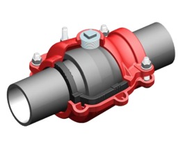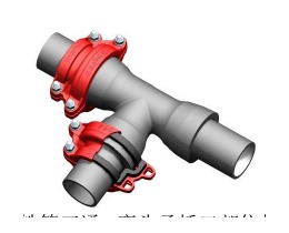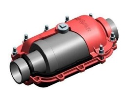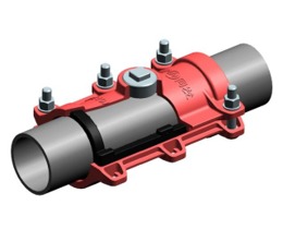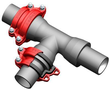
A repair clamp is a pressure-retaining component. Its failure mode is not gradual degradation that announces itself — it is sudden loss of seal, often at maximum system pressure when demand peaks. Understanding how long a clamp lasts and what causes it to fail ahead of its design life is therefore not an academic exercise. It determines whether your repair holds or becomes the next emergency on the same pipe.
Realistic lifespan by material
Clamp body material governs the structural life of the assembly. Gasket material governs the sealing life. These age on different schedules, and the shorter of the two determines when intervention is required.
| Clamp body material | Soil environment | Expected structural life |
|---|---|---|
| QT450-10 ductile iron, uncoated | Neutral soil (pH 6–8, low conductivity) | 10–15 years |
| QT450-10 ductile iron, epoxy-coated | Neutral to mildly aggressive soil | 20–25 years |
| QT450-10 ductile iron, zinc + epoxy | Moderately aggressive soil | 20–25 years |
| SS304 stainless steel | Non-coastal, no chloride exposure | 25–30 years |
| SS316 stainless steel | Coastal, high-chloride, marine atmosphere | 30+ years |
| Carbon steel (bolts only, galvanised) | Neutral soil | 15–20 years |
| Carbon steel (bolts only, bare) | Any buried environment | 5–10 years |
The 20–25 year figure for coated DI is the number most utility engineers should plan around. A DN200 repair clamp installed in 2025 in neutral-pH clay soil with zinc-epoxy coating has a reasonable expectation of structural integrity through 2045–2050 if installed correctly and inspected at 5-year intervals.
The caveat is installation quality — a clamp installed in aggressively corrosive conditions (saline soil, stray-current zones, acid groundwater below pH 5.5) can fail structurally in 5–8 years regardless of coating. More on this below.
Gasket lifespan: EPDM vs NBR
The gasket typically sets the sealing life ceiling. Both common gasket materials age through compression set — the permanent deformation that accumulates under sustained load — and through chemical/UV attack.
EPDM (ethylene propylene diene monomer):
EPDM is the standard gasket for potable water, wastewater, and cooling water clamps. In buried, shielded-from-UV conditions:
- Compression set (ASTM D395 Method B) for quality EPDM: typically 15–25% after 70 hours at 70°C — in service life terms this translates to meaningful resilience loss starting at roughly 15–20 years
- Ozone resistance: excellent (relevant for above-ground or poorly-backfilled installations near electrical equipment)
- Temperature range: −30°C to +120°C continuous; brief excursions to +150°C acceptable
- Expected sealing life buried: 20–25 years in water service
- Expected sealing life above-ground: 12–18 years due to UV and ozone exposure
NBR (nitrile butadiene rubber):
NBR is required for gas, diesel, petroleum, and oil service. It is incompatible with ozone and degrades faster under UV than EPDM.
- Compression set: similar to EPDM at 15–25% after 70 hours at 70°C
- Oil and fuel resistance: excellent
- Ozone/UV resistance: poor — NBR gaskets above ground should be protected or replaced on a 10-year cycle
- Temperature range: −40°C to +100°C continuous
- Expected sealing life buried, gas service: 15–20 years
- Expected sealing life above-ground, gas service: 8–12 years
FKM (Viton):
FKM is used in chemical and high-temperature applications. Significantly more expensive than EPDM or NBR but with a 30+ year sealing life in buried service and much wider chemical compatibility. Specify FKM when fluid temperatures exceed +120°C or when the pipe carries aggressive chemicals.
Failure modes in detail
1. Gasket creep and compression set
This is the most common failure mode in properly installed clamps that have reached their sealing life. Rubber under sustained compressive stress gradually takes on permanent deformation (compression set). Over 15–25 years, the gasket loses enough resilience that it no longer maintains the contact stress needed to prevent leakage — especially when system pressure fluctuates.
Indicators: slow seep at the gasket-pipe interface; leak that appears during pressure surge events and self-seals at lower pressure; bolt torque within specification but leakage present.
Response: replace the gasket. In most clamp designs the shell can be reused if it is structurally intact. Order replacement gasket kits and re-torque to specification. If the clamp is more than 20 years old, assess the shell for corrosion before deciding to reuse it.
2. Bolt corrosion
Bolts are the highest-risk component in a buried clamp because they are the thinnest section of metal exposed to the soil environment. A DN300 clamp bolt is typically M20 or M24 stainless or high-tensile galvanised carbon steel. Uncoated carbon steel M20 bolts in moderately corrosive soil can lose 30–40% of cross-section in 10 years.
Indicators: visible rust staining at the bolt/nut interface during excavation; inability to achieve specified torque (bolt stretching); snap-off of a bolt during re-torque (sudden loss of tension).
Response: replace all bolts as a set. Never replace one bolt in a multi-bolt clamp without replacing the others — differential bolt tension causes uneven gasket compression and leakage at the undertightened side.
Specify SS304 bolts as the minimum for any buried application. SS316 for coastal zones. If the original installation used carbon steel bolts, plan a bolt replacement every 10–12 years regardless of visible condition.
3. Shell corrosion and thinning
Uncoated or de-coated DI shells in aggressive soil (acidic peat, saline ground, stray-current zones) corrode from the outside in. The internal surface is protected by contact with water or the pipe surface, but the external faces and the rib sections are exposed.
Indicators: pitting visible on shell surface during excavation; shell wall measurably thinner than original (use ultrasonic thickness gauge — typical DI shell starts at 8–12 mm wall depending on DN); flaking or blistering of epoxy coating.
Response: replace the clamp. A shell with external pitting to 3 mm depth on an original 10 mm wall has lost 30% of structural cross-section — it should not remain in service at rated pressure.
Preventive: when excavating for any reason near a buried clamp, use the opportunity to assess coating condition. If the coating is blistered, touch-up epoxy or remove and recoat before backfilling.
4. Gasket displacement during installation
Not strictly a service-life failure, but the most common reason for a clamp to fail within the first 6 months after installation. The gasket migrates out of the gasket groove during bolt tightening — usually because:
- The pipe surface was not cleaned before installation
- The gasket was not lubricated with the correct assembly lubricant (silicone-based, not petroleum-based)
- Bolts were tightened on one side only before the opposite side, pulling the clamp off-square
- Wrong gasket profile (e.g., flat gasket on a socket clamp that requires a profile gasket)
Indicators: immediate or early (within days) leakage after installation; uneven bolt tension across the bolt set; gasket visible outside the gasket groove at inspection.
Response: remove, inspect, and reinstall. Do not attempt to stop the leak by further torquing — the gasket is already displaced and additional torque will damage it further.
5. Shell cracking
Brittle fracture of the DI shell is rare in QT450-10 — the 10% elongation of this grade gives it significant capacity to deform before fracture. Shell cracking is more common in:
- Grey iron clamps (legacy product, no longer supplied by major manufacturers)
- QT500-7 or harder grades used in low-cost product
- Impact damage during installation (dropped clamp, struck by excavator bucket)
- Freeze-thaw cycles in above-ground applications where the clamp is filled with water that freezes
Indicators: visible crack in shell; sudden depressurisation with no prior warning.
Response: replace immediately. A cracked shell is not repairable.
Inspection checklist
This checklist is structured for a 5-year periodic inspection, which is the interval most utility maintenance programmes use for clamps installed on critical mains.
Visual inspection (at excavation):
- Coating intact — no blistering, flaking, disbondment
- No visible rust staining from shell (surface rust on bolts is normal and does not indicate structural loss)
- No visible pitting or thinning on shell ribs or flanges
- No visible cracks in shell
- Gasket not extruded outside gasket groove
- No evidence of leak (staining, mineral deposit, wet soil immediately around clamp)
Bolt condition:
- All bolts present and correctly engaged in nuts
- No visible thread stripping
- No bolt snap-off marks (indicating previous overtorque failure)
- Nuts fully engaged — minimum 3 thread protrusions past nut face
Torque check:
- Apply torque wrench at specified installation torque (see table below)
- Record torque achieved vs. specified — any bolt requiring less than 90% of specified torque to reach the mark should be investigated for thread condition
UT thickness check (if warranted by coating condition):
- Measure shell wall thickness at 3 points on each half-shell with ultrasonic gauge
- Compare to nominal wall thickness from product datasheet
- Flag if measured thickness is less than 75% of nominal at any point
Torque specifications by DN
Correct installation torque is the single most controllable factor in clamp service life. Undertorquing leaves the gasket insufficiently compressed — it will leak under surge pressure. Overtorquing damages the gasket and can crack brittle pipe.
| DN range | Bolt size | Torque (standard DI pipe) | Torque (PE/plastic pipe) |
|---|---|---|---|
| DN40–DN80 | M12 | 30–40 N·m | 20–25 N·m |
| DN100–DN150 | M16 | 60–80 N·m | 40–50 N·m |
| DN200–DN300 | M20 | 100–130 N·m | 70–90 N·m |
| DN400–DN600 | M24 | 160–200 N·m | 110–140 N·m |
| DN700–DN1000 | M27–M30 | 220–280 N·m | 150–190 N·m |
| DN1200–DN2000 | M33–M36 | 300–400 N·m | 200–260 N·m |
Torque values are for lubricated bolts (molybdenum disulfide or copper paste on threads). Dry torque requires 10–15% higher values to achieve the same clamp force.
Tighten in cross-pattern sequence (opposing bolts alternating) in three stages: 30% of target, 70% of target, final target. Never run one bolt to full torque before setting the others.
Re-torque vs. replacement decision
This is the practical question maintenance crews face when they excavate a leaking clamp. Use this decision framework:
Re-torque is appropriate when:
- Clamp age is less than 15 years
- Coating is intact
- Bolts are SS304 or SS316 in good condition
- No visible gasket extrusion or cracking
- Torque check shows bolts are at less than 70% of specified value (indicating relaxation, not damage)
- No mineral deposits or crystallisation at gasket-pipe interface
Replace the gasket when:
- Clamp age is 15–20 years
- Re-torque does not stop the leak
- Gasket is visible outside the groove (displacement)
- Gasket surface shows cracking, splitting, or surface crazing visible on inspection
Replace the whole clamp when:
- Clamp age is greater than 20–25 years (DI) or 25–30 years (SS304)
- Shell wall thickness UT measurement shows loss greater than 25% of nominal
- Shell surface shows pitting deeper than 3 mm
- Any bolt has snapped during attempted re-torque
- Coating is completely disbonded and shell surface is fully corroded
- Product model is legacy or discontinued with no gasket kit available
How installation quality affects lifespan
A correctly installed clamp at the bottom of the range (15 years for coated DI) can be extended to the top of the range (25 years) by good installation practice. Conversely, a poor installation can fail within 5 years regardless of product quality.
Pipe surface preparation: The pipe surface under the gasket must be clean and free of scale, bitumen, paint, and loose material. Wire brush or grind the surface. For corroded DI pipe, spot-grind to bare metal in the gasket contact zone. Rough corrosion product under the gasket creates leak paths that torque cannot seal.
Gasket lubrication: Apply gasket lubricant (silicone grease, never petroleum-based) to both the gasket and the pipe surface at the contact zone. This allows the gasket to seat correctly during tightening without rolling out of the groove.
Clamp alignment: The clamp shell must be centred over the leak. On socket joints, the socket clamp must span the full bell-and-spigot joint with the gasket entirely within the joint zone. Misaligned clamps that position the gasket over a casting seam or flange face will leak.
Bolt tightening sequence: Cross-pattern, three-stage tightening (see torque table above). Field practice of running each bolt to full torque before the next is the most common installation error and produces non-uniform gasket compression.
Backfill: Avoid large stones or angular fill material within 150 mm of the clamp. Compact backfill in 200 mm layers. Poorly compacted backfill allows pipe movement that cycles the clamp under bending stress — this is a significant factor in service life, particularly on plastic pipe where pipe flexibility means the clamp experiences continuous movement.