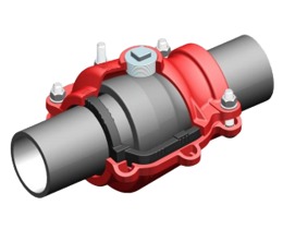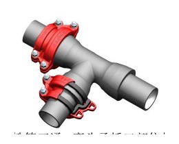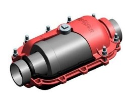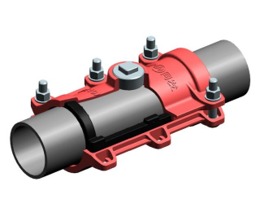
This checklist is written for the crew lead who takes the call at 2 AM. It assumes you know how to operate a wrench and a torque tool. It does not assume you have a perfect GIS map, pristine drawings, or a full day to plan. It is ordered the way a real response unfolds — isolation first, then information gathering, then the repair, then documentation.
Print it, laminate it, put it in the truck.
Phase 1: The first 15 minutes
These tasks run in parallel where possible. Get the site safe before anything else.
On the call (dispatch):
- Record exact location (cross street, address, nearest landmark, GPS coordinates if available)
- Record visible indicators: geyser, flooding, low-pressure complaints, visible sinkhole, construction damage report
- Ask: any known hazards? (adjacent gas, electric, traffic, stream, collapse risk)
- Confirm crew composition: minimum crew lead + two technicians for most breaks; add traffic control if road is involved
- Confirm service truck is stocked with A-item clamps for the grid’s typical main sizes (see stockpile section at the end of this post)
On arrival — immediate hazard check:
- Scan for active hazards: flowing water undermining road surface, gas odour, downed wires, traffic
- If gas odour present: do not excavate. Call gas utility and wait for clearance.
- If downed wires: call electric utility and stage outside hazard zone.
- Establish traffic control or call for it before any crew enters the work zone
- Mark the perimeter; do not allow vehicles on water-saturated pavement until assessed
Locate and call for utility marks:
- Call the one-call centre (811 in the US) if excavation is needed and marks are not already on the ground
- Identify upstream and downstream valves on the distribution map
- Walk the map: confirm valve status (open/closed, last exercised date if known)
Isolate the section:
- Close upstream valve — turn slowly (surge risk on fast closure)
- Close downstream valve
- Open downstream hydrant to relieve pressure and confirm isolation
- Confirm pressure drops to zero. If not, identify the parallel feed path and close additional valves.
- Do not excavate until isolation is confirmed — a pressurised pipe in an active excavation is a safety hazard
Phase 2: Information you need before ordering a clamp
Never order a clamp based on nominal DN alone. Clamps are sized to actual outside diameter, and OD varies by pipe class, manufacturer, and age. Wrong clamp = wasted trip back to the yard.
Pipe identification:
- What is the pipe material? (ductile iron, grey cast iron, PE, PVC, steel, asbestos cement, concrete)
- Is there a pipe stamp or casting mark visible on exposed pipe? Record it.
- What is the pipe class or pressure rating if known from drawings? (e.g., K9, C25, SDR17)
- Year of installation if known (relevant for cast iron condition assessment)
Pipe measurement:
- Measure the outside diameter with calipers. Do not estimate. Do not use the nominal DN from the drawing without confirming.
- For reference: DN100 DI is typically 118 mm OD; DN150 is typically 170 mm; DN200 is typically 222 mm; DN300 is typically 326 mm. These vary — measure.
- If calipers are not on the truck, use a circumference tape (pi tape) and calculate OD = circumference / π. Wrap the tape tightly, avoid the joint bell.
Leak characterisation:
- What is the leak type? (circumferential crack, longitudinal split, pinhole, joint failure, corrosion blowout)
- What is the approximate crack/defect length? (determines whether clamp body length is sufficient)
- Is the failure at a joint (bell-and-spigot, mechanical joint, flanged joint) or on the straight barrel of the pipe?
- Is there visible wall thinning or section collapse? If so, a clamp repair may be temporary at best — plan a section replacement.
System pressure:
- What is the normal operating pressure at this location? (from SCADA, pressure zone map, or nearby hydrant static pressure)
- Is this a fire-flow main (1.0 MPa design pressure) or a transmission main (potentially higher)?
Phase 3: Field sizing when drawings are not available
Drawings are unavailable, the GIS system is down, and the pipe is already exposed. Here is the field sizing method:
Step 1: Identify the pipe material from visual inspection.
| What you see | Material |
|---|---|
| Reddish-brown, heavy wall, visible casting seam | Grey cast iron (pre-1970s) |
| Dark grey, smooth surface, heavy wall, may have cement lining visible at cut | Ductile iron (post-1970s) |
| Black or blue, flexible, continuous (no casting seam), smooth | PE (polyethylene) |
| Grey, rigid, brittle fracture face | PVC or asbestos cement |
| Silver-grey, magnetic, mill scale or weld visible | Steel |
| Grey, very heavy, aggregate visible | Concrete |
Step 2: Measure the OD and identify the clamp type needed.
| Leak location | Clamp type |
|---|---|
| Mid-barrel of pipe (straight section) | Straight pipe repair clamp |
| At a bell-and-spigot socket joint | Socket repair clamp (covers the bell + spigot overlap) |
| At a mechanical joint gland | Socket repair clamp or mechanical joint clamp |
| Circumferential crack at barrel | Straight clamp — verify length covers crack + 75 mm each side |
| Longitudinal split longer than clamp body | Two overlapping straight clamps or section replacement |
| Pinhole / corrosion pit | Straight clamp; address root cause (cathodic protection, soil corrosivity) |
Step 3: Select clamp length.
For a straight pipe repair clamp, the clamp body must cover the defect with a minimum of 75 mm of sound pipe on each side. Standard body lengths:
- Short: 150–200 mm total — for small pinholes and corrosion pits
- Standard: 300 mm total — covers most single circumferential cracks
- Long: 500–600 mm total — for longitudinal splits and multiple adjacent defects
Step 4: Confirm pressure class.
- 1.0 MPa (PN10) clamp for municipal water distribution at normal pressure
- 1.6 MPa (PN16) clamp if main is known to operate above 1.0 MPa or is a transmission main
Step 5: Select gasket.
- EPDM: potable water, treated wastewater, most water service
- NBR: natural gas, petroleum, oil — not for potable water
- Do not mix up. An EPDM gasket on a gas line is a code violation in most jurisdictions.
Phase 4: Clamp installation steps
Pre-installation:
- Confirm the right clamp (OD match, type match, pressure class, gasket material)
- Inspect the clamp — check gasket is seated fully in the groove, no damage, no missing hardware
- Gather: calibrated torque wrench, wire brush or scraper, clean rags, gasket lubricant (if specified)
- Clean the pipe surface at the repair zone: bare metal for DI/steel; bare pipe wall for PE/PVC. Remove soil, rust scale, old coating, and debris. This is the most commonly skipped step, and skipping it is the most common cause of repair failure.
- If the pipe surface has deep pitting or corrosion, apply a compatible pipe repair putty to fill voids before clamp placement.
Installation:
- Centre the clamp body over the defect. The defect should be within the gasket seating zone, not at the edge.
- Assemble clamp halves around the pipe. Hand-tighten all bolts until the gasket contacts the pipe surface.
- Tighten bolts in cross pattern, not sequentially around the bolt circle. This is critical for even gasket compression.
- Stage 1: tighten to approximately 30% of final torque, cross pattern
- Stage 2: tighten to approximately 60% of final torque, cross pattern
- Stage 3: tighten to 100% of final torque, cross pattern
- Stage 4: full circuit of all bolts at 100% torque to confirm no relaxation
- Gasket visual check: gasket should be visible at the clamp edges but should not extrude beyond the clamp body. If gasket is extruding significantly, over-torque is likely — back off and reinvestigate.
Torque reference (typical values — always use the manufacturer’s specification):
| Bolt size | Typical final torque (N·m) | Applies to |
|---|---|---|
| M12 | 30–50 | Small clamps, DN50–DN100 |
| M16 | 60–90 | DN100–DN200 clamps |
| M20 | 100–140 | DN200–DN400 clamps |
| M24 | 160–200 | DN400–DN600 clamps |
| M30 | 250–320 | DN600–DN1000 clamps |
Do not use these values as a substitute for the manufacturer’s torque table. They are a sanity check only — if the manufacturer specifies a different value, use the manufacturer’s value.
Phase 5: Pressure test protocol after repair
Never re-pressurize rapidly. Water hammer from sudden pressurization can dislodge a correctly installed clamp or damage adjacent fittings. The 3-stage ramp protocol:
- Close the downstream hydrant that was used for depressurization (or reduce it to a small bleed to allow air purging)
- Open upstream valve to approximately 20% of full open. Hold for 60 seconds. Inspect clamp for weeps.
- If dry: open upstream valve to approximately 50%. Hold 60 seconds. Inspect.
- If dry: open upstream valve to 100%. Hold 60 seconds. Final inspection.
- If there is a leak at any stage: close the valve and depressurize before investigating. Do not attempt to re-torque under pressure. Re-torqueing a leaking clamp under pressure masks the problem and can cause sudden failure.
If the clamp leaks after re-pressurization:
- Depressurize the section
- Remove the clamp
- Re-inspect the pipe surface and gasket
- Most causes of seal failure: pipe surface contamination, gasket mis-seated in groove, wrong OD (clamp too large for the pipe)
- Re-install with surface properly prepared
Confirming successful repair:
- No visible weeping or dripping at clamp body, gasket edges, or bolt penetrations after 5 minutes at full pressure
- Verify pressure with a gauge on a nearby hydrant or service — confirms the section is holding
- Close the bleed hydrant fully
- Notify dispatch: line is pressurized and holding
Phase 6: Documentation requirements
Documentation is not optional. A poorly documented repair creates liability exposure when the repair fails, creates scheduling problems for follow-up work, and prevents pattern analysis (repeated breaks at the same location are a sign of a systemically failing asset).
Minimum documentation for every repair event:
- Date and time of notification
- Date and time of isolation
- Date and time of restoration
- Location (address, GPS coordinates, map reference)
- Pipe material, nominal DN, measured OD
- Pipe age if known
- Failure mode (crack type, location on pipe, probable cause if determinable)
- Clamp type installed (manufacturer, product reference, DN, body length, gasket material)
- Torque applied (N·m) and torque wrench ID number
- Crew names and IDs
- Photographs: pipe surface before cleaning, pipe surface after cleaning, clamp installed, pressure test in progress
Photographs to take:
- Wide shot showing the excavation and pipe location in context
- Close-up of the defect before cleaning
- Close-up of the pipe surface after cleaning, before clamp installation
- Clamp installed, before pressurization
- Pressure gauge reading after full pressurization
Load into the maintenance management system (CMMS) before end of shift. This is not a next-day task. If it is not entered while the repair is fresh, details are lost.
Flag for follow-up if:
- Visible wall thinning or section loss was observed (schedule condition assessment or planned replacement)
- Break is the second or third at this location in the past 24 months (segment replacement may be warranted)
- Pipe material is grey cast iron (inherently brittle; recommend assessment of adjacent pipe condition)
- Soil conditions showed highly aggressive signs (sulfate odour, low pH, high conductivity)
Phase 7: Stockpile recommendations
The fastest emergency repairs happen when the right clamp is already on the truck. Based on typical North American and European urban distribution grids:
A-items (stock 2–3 per truck, 5–10 in warehouse):
- DN100 socket repair clamp, DI type, 1.0 MPa
- DN100 straight pipe repair clamp, DI type, 1.0 MPa
- DN150 socket repair clamp, DI type, 1.0 MPa
- DN150 straight pipe repair clamp, DI type, 1.0 MPa
- DN200 socket repair clamp, DI type, 1.0 MPa
- DN200 straight pipe repair clamp, DI type, 1.0 MPa
B-items (stock 1 per truck, 2–3 in warehouse):
- DN80 socket and straight clamps, DI
- DN300 socket and straight clamps, DI
- DN100 socket and straight clamps, PE/PVC type (if plastic mains are in the grid)
- DN200 socket and straight clamps, PE/PVC type
C-items (0–1 in warehouse; confirm supplier 72-hour availability for larger sizes):
- DN400, DN500, DN600 — warehouse stock only; evaluate against break frequency
- DN800 and above — do not stock unless your grid has a significant number of this size; maintain a supplier relationship that allows 3-day delivery
Tools that must be on every repair truck:
- Calibrated torque wrench(es) covering the torque range for the carried clamp sizes
- Calipers or pi tape — pipe OD measurement
- Wire brush and scraper — pipe surface prep
- Clean rags — surface wipe-down before gasket placement
- Headlamp and work light — repairs happen at night
- Camera or phone for documentation photographs
- Pressure gauge (0–1.6 MPa range) with hydrant adapter
Gasket shelf life check before deployment: EPDM gaskets in sealed packaging have a typical shelf life of 5–7 years at ambient temperature. Gaskets stored on trucks in high-temperature summer conditions degrade faster. Inspect gasket condition (surface cracking, loss of elasticity) on any clamp that has been in truck stock for more than 3 years. Replace the gasket before deployment, not during the repair.
Quick reference: clamp sizing by pipe OD
| Measured OD (mm) | Nominal DN (approx.) | Pipe material (typical) |
|---|---|---|
| 60–63 | DN50 | PE, PVC |
| 75–76 | DN65 | DI, PE |
| 90–93 | DN80 | PE, PVC |
| 110–114 | DN100 | PE, PVC |
| 118–122 | DN100 | Ductile iron |
| 140 | DN125 | PE |
| 160–163 | DN150 | PE, PVC |
| 170–174 | DN150 | Ductile iron |
| 200–203 | DN200 | PE, PVC |
| 222–226 | DN200 | Ductile iron |
| 250–255 | DN250 | PE, PVC |
| 274–280 | DN250 | Ductile iron |
| 315–318 | DN300 | PE, PVC |
| 326–332 | DN300 | Ductile iron |
Always measure — these are typical values and vary by manufacturer, pipe class, and country standard. A 4 mm error in OD means the clamp will not seal.